P&ID upgrade for an entire plant
Process safety
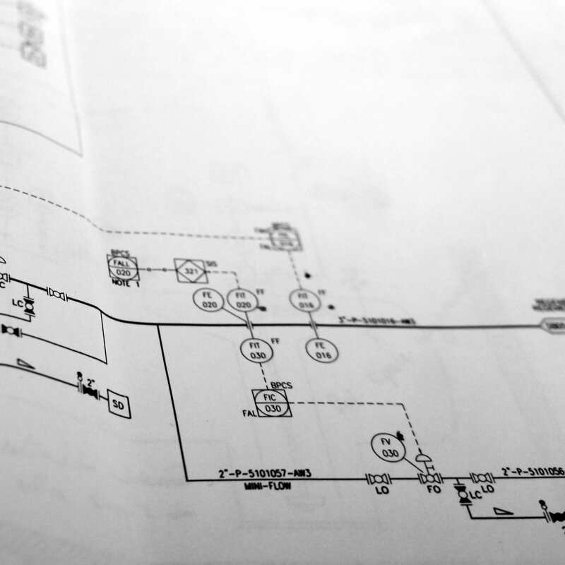
A HAZOP review revealed that the existing PFDs at a Seveso site lacked the detail needed to operate safely and to manage changes in a controlled way. Prohead Engineering turned that recommendation into a complete project: digitising in AutoCAD Plant 3D, field verification and development into unambiguous as-built P&IDs that follow the client's conventions and the relevant P&ID standards.
About the case
Context:
During a HAZOP at a Seveso site, it became clear that the existing PFDs lacked the detail needed for safe operation, management of change and audits. Prohead Engineering digitised the PFDs in AutoCAD Plant 3D and, after field verification, developed them into as-built P&IDs. The client's established practices in nomenclature and symbols were integrated as far as possible and harmonised with EN ISO 10628, EN ISO 20560 and ANSI/ISA-5.1.
Methodology:
Phase 1 – GAP analysis. We assessed all source documents against the actual installation and the standards mentioned above. At an early stage, we agreed how the existing client nomenclature would be mapped onto the P&ID conventions, so that the final drawings would be recognisable and unambiguous for operations and maintenance.
Phase 2 – Site visit and detailed survey. In the field, we systematically recorded line routings, tie-ins, valve positions, instrument hook-ups, relief routes, utility connections and interlocks. We verified mechanical equipment with tag names and connection sizes, all valves and identifications present, process lines including sizes and insulation, line numbers with piping class and diameter, vents and drains, and we marked slopes and spec breaks where the piping class changes.
Phase 3 – Drafting in AutoCAD Plant 3D. The PFDs were developed into complete P&IDs with the required level of detail. The drawings show equipment with tag and nozzle connection size, lines with line number, class and DN/ND, all valves with a unique ID and symbol, all instruments with tag and function code, basic control loops (e.g. LIC/PIC/FIC) and the relevant interlocks, as well as air intake/venting and drain/vent points according to the agreed labelling.
Tagging:
We developed and safeguarded the tagging centrally. The tag structure for equipment, lines and instrumentation follows the existing plant coding and the chosen P&ID conventions. Line IDs include class and diameter, instrument tags match the loop naming, and interlocks and basic control loops are referenced consistently between P&IDs, lists and — where applicable — maintenance or safety files. Thanks to this standardisation, line routings, tie-ins, valve positions, instrument hook-ups, relief routes, utility connections and interlocks can be traced one-to-one in both the drawing and the associated tag and line lists.
Aftercare:
After delivery, we manage the as-built P&IDs through an agreed change process. Updates are made on request or periodically, with targeted walk-downs so that interlocks, loops, line classes, slopes and spec breaks continue to match the actual installation.